
[xyz-ips snippet=”lesson4″]
Introduction
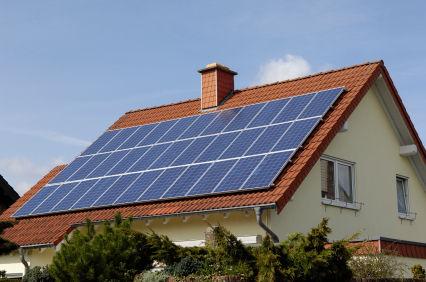
Through the usage of solar panels, we can provide power to the smart house’s many sensors via panels mounted on the roof of the smart house. Setting up the solar panels and utilizing the power generated for powering these devices is quite simple. Each part and how these parts interact will be detailed in the sections below.
Required Parts
The parts needed to implement the solar panel setup are the following:
- [x1/+] Solar Panel: Generates energy to charge the battery; directly connected to the solar charge controller.
- [x1] Solar Charge Controller: Regulates the power coming in from the solar panel, going to charge the battery, and the power being delivered from the battery to the ‘Load’ devices.
- [x1] 12V Battery: The battery that will be charged by the solar panel. The desired size will vary based on power requirements for your system.
- [x1] 12V-to-5V DC Regulator: Converts the 12V of the Solar Panel to a microcontroller & (most) devices friendly voltage of 5V.
- [x1] Current Sensing Module: This module is used to calculate just how much power the solar panel is generating to charge the battery.
These parts will be more specifically detailed in their respective sections below.
Solar Panel
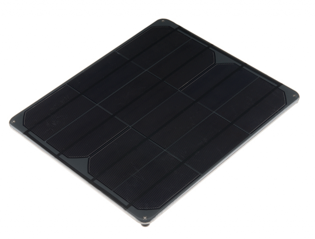
For this project, we have settled on using a solar panel around the following parameters:
What Is It & Why?
The Solar Panel is the key component for supplying solar power to the Smart Home devices. Solar Panels come in many different sizes and power ratings and must be chosen based on the needs of the project and overall power consumption of the targeted devices. We opt to add a solar power option to the Smart Home project as the usage of solar is better for the environment and will continue to be a growing source of energy as we advance solar technology.
Since the panel will be used to charge a chosen battery, we will also need to find out just how much energy our battery can store. This can be calculated via the following method:
X = Battery Size in Amp Hours Y = Battery Voltage Z = Power Available In Watt Hours
X * Y = Z
Example Calculation
For a 20AH, 12V battery the Watt Hours figure is 20(X) x 12(Y) = 240 WH (Z)
- This means that the battery could supply 240W for 1 hour, 120W for 2 hours, or even 2W for 120 hours.
- Clearly put: The more energy you take, the faster the battery discharges
How Much Energy Do I Need? How much energy can a solar panel output over a period of time?
The answer to this question varies greatly by the direct sun exposure available, time of year, location, and many more factors, but here is a general idea:
- If you required 196W of power generated in the FALL time, assuming 6 hours of sunlight each day:
- Watts required / time of year sunshine hours = PANEL SIZE (i.e. 196W/6hrs = 32.6W panel)
- If you required 196W of power generated in the WINTER time, assuming 6 hours of sunlight each day:
- Watts required / time of year sunshine hours = PANEL SIZE (i.e. 196W/1hrs = 196W panel)
Solar Charge Controller
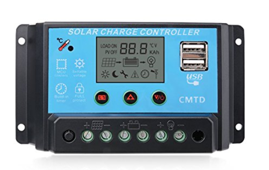
In order to use the solar panel to meet our needs, we will need to employ the aid of a ‘Solar Charge Controller’. This device handles the communication between the SOLAR PANEL, BATTERY, and LOAD.
- SOLAR PANEL: The solar panel will connect to the left-most [+] and [–] screw terminals on the controller and this will pass in the power generated by the panel to the charge controller.
- BATTERY: The middle [+] & [–] screw terminals are where we will connect the battery that will power the IoT Smart House devices. This battery will be charged by the solar panel through this controller.
- LOAD: The far right two pins, [+] & [–] respectively, are where we will connect our load. Since the Solar Panel output voltage is 12V, we must use a regulator if we want to use devices that are 5V.
- Instead of directly connecting our load, we will connect a voltage regulator to drop the 12V from the solar panel to a microcontroller-friendly 5V level. Any generic 12V-5V regulator can be used here, but we opted for one with x2 USB Ports for easier usage.
Battery
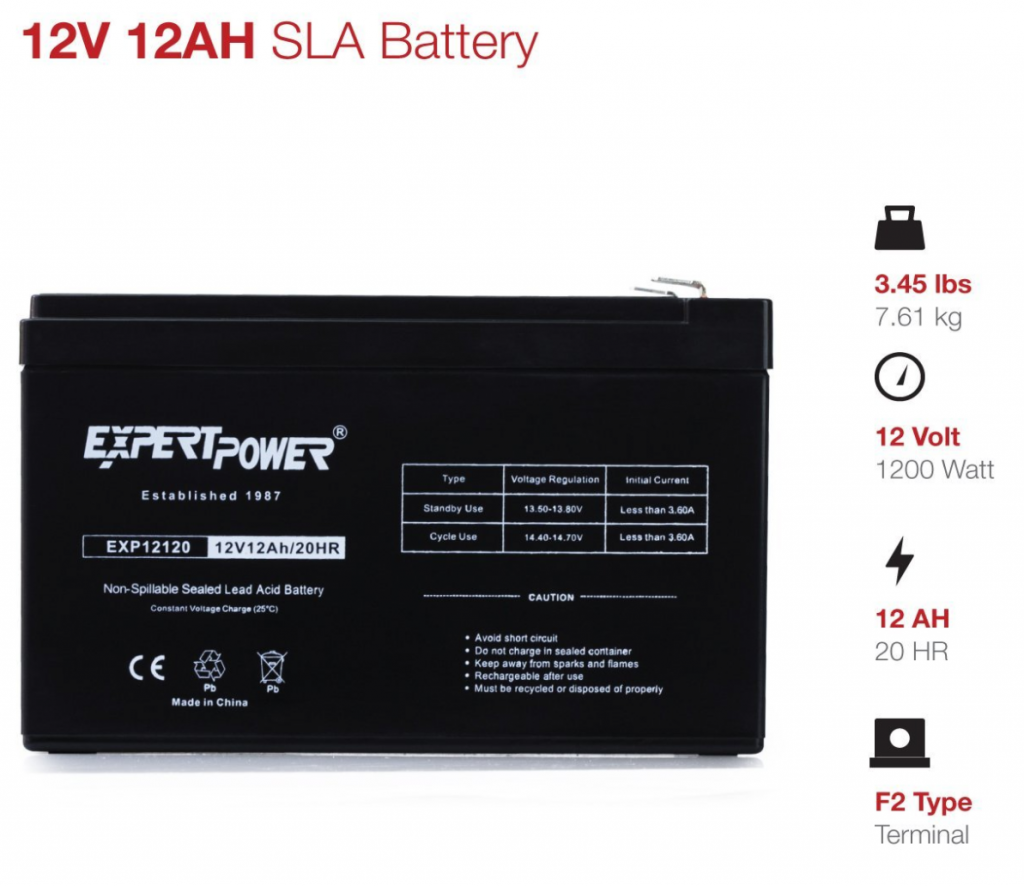
We could aim to just power our targeted devices via strictly solar, but what happens when the sun sets and power generation comes to a screeching halt? This is where a battery comes in handy and is why we use one in our solar setup.
As described in ‘Section 1.3’, the battery is directly connected to our ‘Solar Charge Controller’ via the [+] and [-] screw terminals. The particular battery used can vary based on the power needs of your project, but for this example we opted to use a 12V battery rated around 12AH (amp hours):
It is important to choose a battery size that is higher than the needed amount in the case of lower solar generation due to weather and other issues that could arise in solar power generation. I.e. if your project requires a 12AH battery, it may be wiser to opt for a 15AH battery or larger.
12V-to-5V Regulator
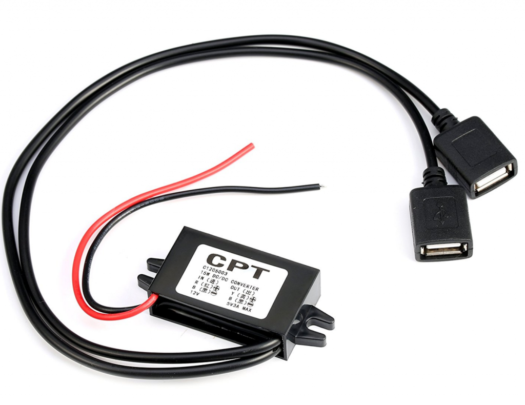
This device is a voltage regulator. It essentially takes the 12V of the battery and converts it down to 5V so that we can use it with our microcontrollers (such as the UNO) and other devices that require 5V logic levels. This is what we will hook up to the load portion of the ‘Solar Charge Controller’ and using the two provided USB ports, power our devices.
Many different types of these regulators exist, but the key functionality we’re aiming for is the 12V-5V regulation and multiple USB ports for convenience. The output of the specific one that we are using is 5V-3Amps.
Current Sensing Module
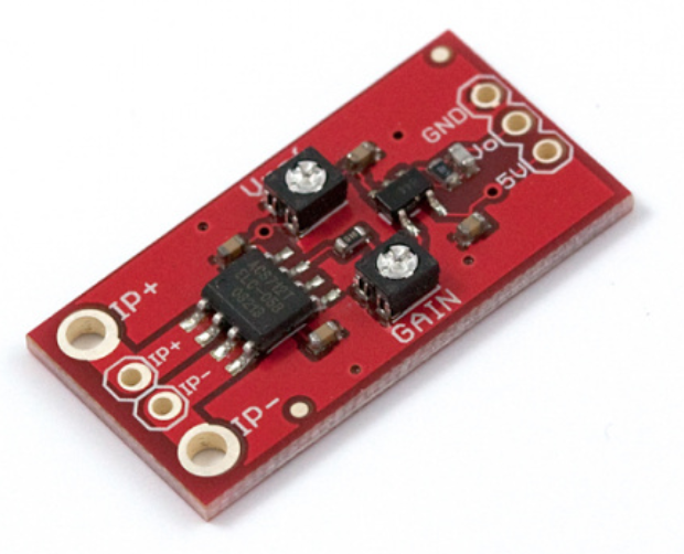
We will be using a different current sensing module from Adafruit. This section will be updated once we have implemented it into our design.