
[xyz-ips snippet=”lesson5″]
General Servo Information
One key component of a smart home is the ability to automate certain tasks that make the lives of those living in the home easier. One way that we can automate certain tasks is by using motors, in this case, servo motors.
The two most common types of servos are SG90 9G micro servos, which only move about 180 degrees (usually a bit below that) and continuous servos, which can move a full 360 degrees in either clockwise our counter-clockwise directions nonstop.
Continuous motion servos are generally more expensive, but are necessary if your design requires spin for more than 180 degrees. Both of these servos are pictured below, but they may come in different varieties from various sellers online.
FS90R can be found on ebay as low as $3.74/each, SG90 can be found as low as $1.99/each

SG90 180-deg Servo
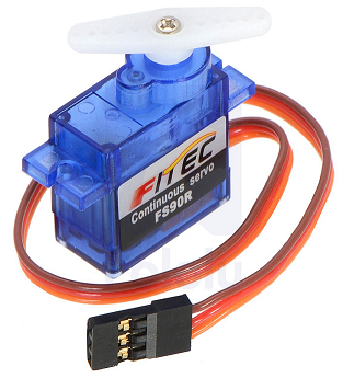
FS90R 360-degree Continuous Servo
Continuous Motion 360 Degree Servo Wiring:
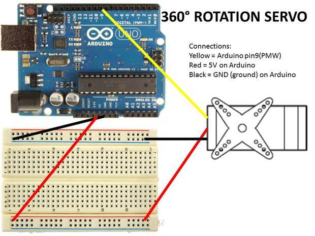
To control a 360 degree- continuous servo motor, you will need to include the following code:
Required Libraries: <Servo.h>
[cc lang=”c” width=”500″ escaped=”true”]
#include <Servo.h>
void setup() {
myservo.attach(9); // Servo conn. to Digital Pin 9 [PWM]
}
void loop() {
myservo.write(180); // Move counter-clockwise full speed
delay(100); // Sets duration of rotation (in ms)
myservo.write(0); // Do not move the servo at all
delay(100); // Sets duration of rotation (in ms)
myservo.write(90); // Move clockwise full speed
}
[/cc]
[Note: The version of the IDE used at this time was 1.8.4]
- 0 = Move full speed in the clockwise direction
- 90 = Do not move at all in either direction
- 180 = Move full speed in the counter-clockwise direction
These values can be adjusted to move the continuous motion servo slower than full speed in either clockwise or counterclockwise directions.
180 Degree Servo Motors Wiring:
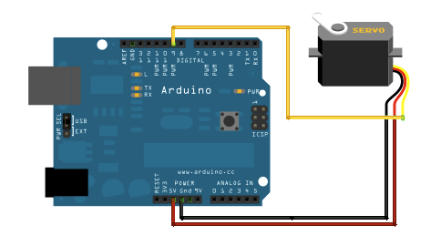
How do SG90 180 degree Servo Motors work?
These 180-degree SG90 Servos are controlled by PWM (Pulse-Width Modulation) signals. Pins without PWM read from 0 to 1, which wouldn’t be very helpful when using a servo that can position itself from 1 degree to 180 degrees. That is why we must use PWM.
The Arduino digital pin that you connect them to MUST support PWM (which is usually denoted by a ~ next to Pin Number on the Arduino).
The Arduino UNO can send up to 6 PWM signals at once, while the Arduino MEGA can handle a huge number.
The SG90 Servo motors have THREE wires:
- Brown = Ground (GND)
- Red = 5V (VCC)
- Orange= PWM Signal (connected to Arduino digital pin)
Now that you have wired up the SG90 Servo motor and have a basic understanding of its operation, we will now go over how to program the Arduino to control it on the next page.
SG90 180-Degree Servo Motor Programming/Code
The programming for the SG90 servos differs from the FS90R continuous motors in that you are telling the servo motor exactly which degree to move to, rather than telling it to turn in a direction for a set amount of time.
The following code example will rotate the servo motor from 0 degrees to 180 degrees by 1 degree increments at a time. When the servo motor has rotated 180 degrees it will start to rotate in the opposite direction until getting back to its home position (set to 0 in this example).
[cc lang=”c” width=”500″ lines=”25″ escaped=”true”]
#include <Servo.h>
Servo test_servo;
int angle = 0;
void setup() {
test_servo.attach(6); // Set to pin servo is attached to
}
void loop() {
// Command to move from 0 degrees to 180 degrees
for (angle = 0; angle < 180; angle += 1) { // Command to rotate the
servo to the specified angle test_servo.write(angle); delay(15);
}
delay(1000); // Command to move from 180 degrees to 0 degrees
for (angle = 180; angle > 0; angle -= 5) {
// Command to rotate the servo to the specified angle
test_servo.write(angle);
delay(5);
}
delay(1000);
}
[/cc]
[Note: The version of the IDE used at this time was 1.8.4]
IoT Smart Home Garage/Elevator Automation
IoT Smart House Automated Garage
Now that we have gone over the 2 Types of servo motors available to us, we can now use them in our Smart House design.
One use for servo motors in our smart house is the automatic control of the garage opening and closing via application or voice control.
Since we will need more than the basic 180-degrees of movement that SG90 servo motors provide, we can use a string tied to a 360-degree continuous servo motor to open the garage, rotating clockwise to open the garage and counterclockwise to close the garage.
Garage is closed
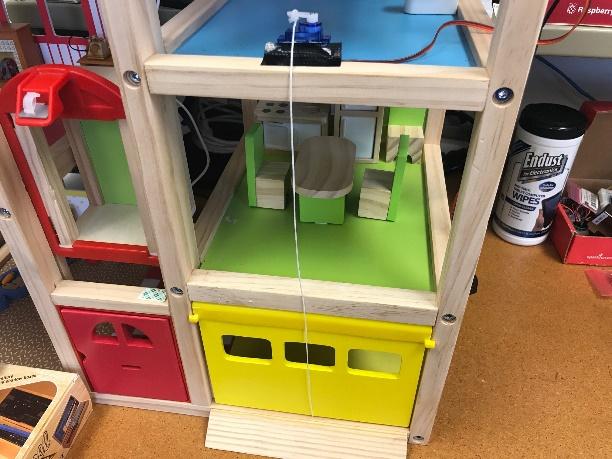
Garage is open after motor rotates
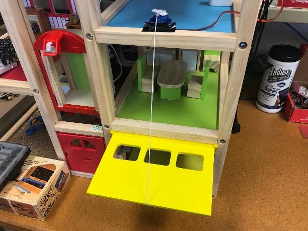
In this simple setup, we have the garage closed and our FS90R mounted above the garage. This design is simply to show the concept and will be altered to hide the string &servo motor in future revisions. When the ‘Open garage’ request is sent to the microcontroller, the servo will rotate and open the garage using the code block below:
[cc lang=”c” width=”500″]
myservo.write(180);
delay(3000);
myservo.write(90);
[/cc]
When the ‘Close Garage’ request is sent to the microcontroller, the servo will rotate and close the garage using the code block below:
[cc lang=”c” width=”500″]
myservo.write(0);
delay(3000);
myservo.write(90);
[/cc]
As mentioned in the prior section on continuous servos, the code for controlling these motors is very simple. Please refer to that section if you need a refresher on how this code works.
IoT Smart House Automated Elevator
The automated elevator uses a similar approach with the FS90R servo motors to rotate one way to pull up the elevator and rotate the other way to drop the elevator (the elevator using this design must be able to free fall to avoid resistance.
This tutorial and explanation is still under construction and this section will be updated once it is complete.
5V Fan Motor Operation
Another household appliance that we can automate using motors is the ‘ceiling fan’ for a room. To scale this down for our Smart House project we are using the ‘IDUINO L9110 Fan Motor Control Module’ pictured below:
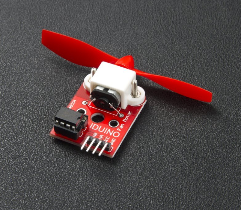
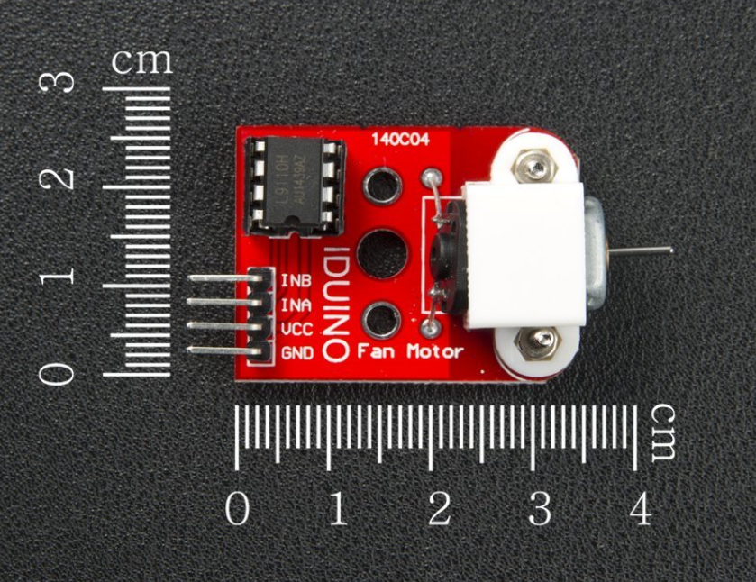
This board uses the L9110 driver to control the speed of the fan with high efficiency. The greater the input current, the faster it will spin. It has the capability to blow out the flame of a lighter from roughly 20 cm away.
We will utilize this board and fan to act as an IoT ceiling fan that can be controlled via voice and/or a smart phone application.
The board has the following pins:
- INB
- INA
- VCC
- GND
INB & INA can be connected to any PWM capable pins on the microcontroller. VCC will be connected to the 5V pin on the microcontroller &GND (ground) will be connected to the GND (ground) pin of the microcontroller. Once this is wired, you can use the code below to use the fan in your design.
IDUINO L9110 Fan Motor Module – Arduino Code
The code below is fairly straight-forward and does not require any additional libraries or files to function. You can set the INA and INB pins to any compatible PWM pin on the microcontroller.
[cc lang=”c” width=”550″ lines=”18″]
// These pins can be changed to other PWM pins if needed
int INA = 9; // This is the pin that input A (INA) is connected to
int INB = 10; // This is the pin that input B (INB) is connected to
void setup() {
pinMode(INA, OUTPUT);
pinMode(INB, OUTPUT);
}
void loop() {
// This will turn the fan on and spin (INA, INB allow cw or ccw)
analogWrite(INA, 255);
digitalWrite(INB, LOW);
// Setting INA and INB LOW will turn off the fan
digitalWrite(INA, LOW);
digitalWrite(INB, LOW);
}
[/cc]