
[xyz-ips snippet=”lesson6″]
Introduction
Another important device to automate in the Smart Home is the lighting system. We can simulate actual light bulbs by using individual LEDs and wiring them up to our Arduino/microcontroller.
We can use two major types of LEDs, single color, and RGB.
LEDs
Single Color LEDs
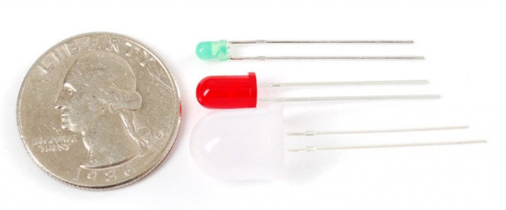
Single Color LEDs work as they sound, they produce 1 color and usually come in 3mm, 5mm, and 10mm sizes.
RGB LEDs
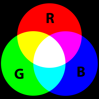
RGB LEDs can produce a multitude of colors since they combine red, blue, and green to produce over 16 million hues of light. On a side note, pigment colors such as Brown or Pink are difficult or impossible to produce.
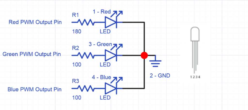
Since there are actually THREE LEDS, one red, one green, and one blue inside, the brightness of each of the individual LEDs can be set to mix pretty much any color that is desired.
We set the brightness for each internal LED by using resistors, but this can be difficult if you want to experiment with colors or easily change the brightness values.
To get around using resistors for setting the brightness, we can utilize the PWM pins marked with a ~ on the Arduino digital pins.
The PWM pins will allow us to output a variable amount of power to the appropriate LEDs.
RGB LED Programming Arduino Code
[cc width=”500″ lines=”43″ lang=”c”]
/*
Adafruit Arduino – Lesson 3. RGB LED
*/
int redPin = 11;
int greenPin = 10;
int bluePin = 9;
// Uncomment this line if using Common Anode LED
//#define COMMON_ANODE
void setup() {
pinMode(redPin, OUTPUT);
pinMode(greenPin, OUTPUT);
pinMode(bluePin, OUTPUT);
}
void loop() {
setColor(255, 0, 0); // red
delay(1000);
setColor(0, 255, 0); // green
delay(1000);
setColor(0, 0, 255); // blue
delay(1000);
setColor(255, 255, 0); // yellow
delay(1000);
setColor(80, 0, 80); // purple
delay(1000);
setColor(0, 255, 255); // aqua
delay(1000);
}
void setColor(int red, int green, int blue) {
#ifdef COMMON_ANODE
red = 255 – red;
green = 255 – green;
blue = 255 – blue;
#endif
analogWrite(redPin, red);
analogWrite(greenPin, green);
analogWrite(bluePin, blue);
}
[/cc]
This example code allows us to utilize an RGB LED that is connected to pins 9, 10, and 11. These pins support PWM, therefore we can easily adjust their individually delivered power to create colors that we desire.
Extra Details and Information can be found on Adafruit’s website: https://learn.adafruit.com/adafruit-arduino-lesson-3-rgb-leds/overview
Piezo Buzzer
A piezo buzzer is a component with a material having piezoelectric ability. Piezoelectricity is the ability for a material to produce voltage when it gets distorted.
Alternatively, if you produce a voltage, the material gets distorted. When you stop producing a voltage, the material will return to its original shape. When you vary the voltage on/off setting, the piezo will start to oscillate and produce a sound.]
You can adjust the volume of a piezo buzzer by connecting a resistor in series between the ‘+’ connection of the Piezo buzzer and the digital pin on the Arduino.
A ‘LARGER’ resistance value will lead to a quieter sound, while a “SMALLER” resistor value will lead to a louder sound.
Piezo Buzzer Circuit – NO RESISTOR – MAX VOLUME
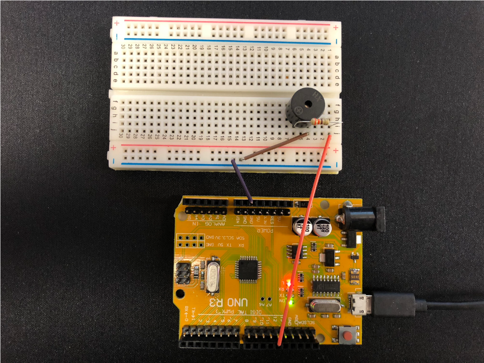
Piezo Buzzer Circuit – 330 Ohm Resistor – A bit quieter than MAX volume
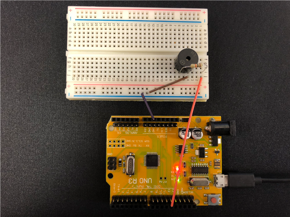
Piezo Buzzer Circuit – 10K Ohm resistor – Very Quiet sound
Generating Different Tones
You can generate different tones from the piezo buzzer by using the ‘tone(pin, frequency)’ or ‘tone(pin, frequency, duration)’ Syntax.
Parameters
- Pin: the pin we will connect to for generating the tone
- Frequency: the frequency of the tone, measured in Hertz – [unsigned int]
- Duration: how long we will produce the tone, in milliseconds – [unsigned long]
Some Example Tone & Their Corresponding Notes
[cc width=”530″ lang=”c”]
int tones[] = [261, 277, 294, 311, 330, 349, 370, 392, 415, 440];
// mid C C# D D# E F F# G G# A
[/cc]
Wiring
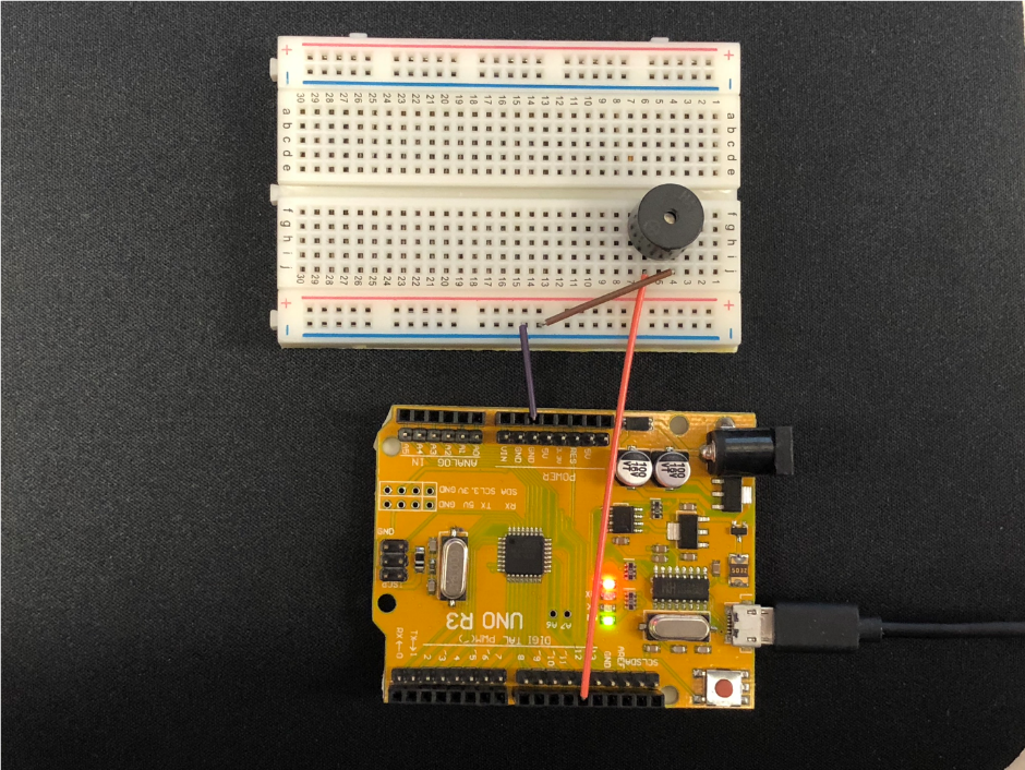
Connecting a piezo buzzer to an Arduino or other microcontroller is fairly simple. You will need to make the following 2 connections:
- GND à Negative Side of Piezo Buzzer (often has a shorter pin on the buzzer for the negative side)
- D12 à Positive Side of Piezo Buzzer (often marked with a ‘+’ symbol on the plastic)
Optional: To adjust the volume of the piezo buzzer, add a resistor in series between the Positive (+) side of the piezo buzzer and the digital pin, in this case, D12.
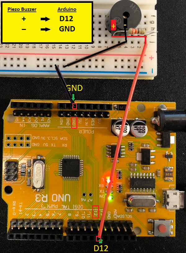
Piezo Buzzer to Arduino Wiring Layout
Arduino Code
[cc width=”550″ lines=”19″ lang=”c”]
/*
Adafruit Arduino – Lesson 10. Simple Sounds
https://learn.adafruit.com/adafruit-arduino-lesson-10-making-sounds/playing-a-scale
*/
int speakerPin = 12;
int numTones = 10;
int tones[] = [261, 277, 294, 311, 330, 349, 370, 392, 415, 440];
// mid C C# D D# E F F# G G# A
void setup() {
for (int i = 0; i < numTones; i++) {
tone(speakerPin, tones[i]);
delay(500);
}
noTone(speakerPin);
}
void loop() {}
[/cc]
[cc width=”550″ lines=”60″ lang=”c” escaped=”true”]
/*
HC-SR04 Ping distance sensor:
VCC to arduino 5v
GND to arduino GND
Echo to Arduino pin 7
Trig to Arduino pin 8
This sketch originates from Virtualmix: http://goo.gl/kJ8Gl
Has been modified by Winkle ink here: http://winkleink.blogspot.com.au/2012/05/arduino-hc-sr04-ultrasonic-distance.html
And modified further by ScottC here: http://arduinobasics.blogspot.com.au/2012/11/arduinobasics-hc-sr04-ultrasonic-sensor.html
on 10 Nov 2012.
*/
#define echoPin 7 // Echo Pin
#define trigPin 8 // Trigger Pin
#define LEDPin 13 // Onboard LED
int maximumRange = 200; // Maximum range needed
int minimumRange = 0; // Minimum range needed
long duration, distance; // Duration used to calculate distance
void setup() {
Serial.begin (9600);
pinMode(trigPin, OUTPUT);
pinMode(echoPin, INPUT);
pinMode(LEDPin, OUTPUT); // Use LED indicator (if required)
}
void loop() {
/* The following trigPin/echoPin cycle is used to determine the
distance of the nearest object by bouncing soundwaves off of it. */
digitalWrite(trigPin, LOW);
delayMicroseconds(2);
digitalWrite(trigPin, HIGH);
delayMicroseconds(10);
digitalWrite(trigPin, LOW);
duration = pulseIn(echoPin, HIGH);
//Calculate the distance (in cm) based on the speed of sound.
distance = duration/58.2;
if (distance >= maximumRange || distance <= minimumRange){
/* Send a negative number to computer and Turn LED ON
to indicate “out of range” */
Serial.println(“-1”);
digitalWrite(LEDPin, HIGH);
}
else {
/* Send the distance to the computer using Serial protocol, and
turn LED OFF to indicate successful reading. */
Serial.println(distance);
digitalWrite(LEDPin, LOW);
}
//Delay 50ms before next reading.
delay(50);
}
[/cc]
HC-SR04 Alternative Wiring / Programming with 3 Pins
You can also use the HC-SR04 Ultrasonic Distance Sensor with only 3 pins by utilizing the NewPing.h library and by shorting the TRIG & ECHO pins (you “short” them by connecting them together) Arduino New Ping library: https://bitbucket.org/teckel12/arduino-new-ping/downloads/
Once you download the library above, add it to your Arduino IDE library folder. The version used in this tutorial for New Ping is v1.8, but there may be a newer library available when you are following this tutorial. Stick with v1.8 in the case of issues.